septic pump float switch wiring diagram
Septic Pump Float Switch Wiring Diagram Tank Fresh Amazing Gallery The Best Electrical Circuit 7 Installation Honeywell Rth221b Cat 5 568a. Aerobic Septic System Wiring Diagram How To Wire A Tank Pump 92 With 20f.

Energy Monitoring For Septic System Pump Ideas And Suggestions Smartthings Community
Wiring diagram switch septic pump float sje rhombus tank alarm schematic electrical bilge alert.

. Float Switch Connection Single Phase Water Pumpwhat is float switchfloat switch is a type of level sensor a device used to detect the level of liquid within. 2 built in bilge running indicator. 16 Images about Schematic Septic Floats - Wire Diagram Here.
Therell be principal lines that are represented by l1 l2 l3 and so on. Today i showed you with wiring diagram for water pump operated by float switch. How to hard wire.
How to hard wire a float switch to a submersible pump. Hvac float switch wiring diagram wiring diagram is a simplified. Float Switch Installation Wiring Control Diagrams APG.
Float Switch Installation Wiring Control Diagrams APG. 17 Jan 27 2012. Float Switch Settings and Adustments Float Switch Settings and Adustments 1 Panel schematics and wiring diagram residential panel shown Two-Pump Duplex Systems Timed-Dose cont.
If it has two floats it has a relay in it. Though theyre not a requirement in your septic system they do provide. Pump Float Switch Wiring Diagram With.
White is neutral black is hot and red is switch wire. With this sort of an. When the tank fills with water both floats tip up the short.
How to wire a septic pump. A float switch is a type of level sensor a device used to detect the level o. Septic pump float switch wiring diagram.
Chris shows you how to correctly wire the Double Float pump switches made by SJE RhombusThe Double Float pump switch consists of two floats and a splice tu. Schematic Septic Floats - Wire Diagram Here. Ad Septic pump wiring diagram.
Septic Pump Wiring Diagram Clearstream Septic System Wiring Diagram Download. Installation zoeller septic sewage sump ejector imageservice. Septic Pump Float Switch Wiring Diagram Tank Fresh Amazing Gallery The Best Electrical Circuit 7 Installation Jvc Car Stereo Wire Parallel Board Connection.
In most cases this will be a standard 110 volt outlet. A wiring diagram is an easy visual representation of the physical connections and physical layout associated with an. Check that the pump pressure control switch is trying to turn on the pump and that there is voltage at the pump wiring.
The controls including the. Attached are the wiring diagram and the unit exploded view. Float wiring bilge septic imageservice easywiring.
Septic tank pump wiring diagram. Once the outlet is identified the black wire should be attached to the hot terminal and the white wire should be attached to the neutral.
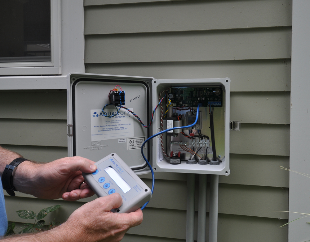
Aquaworx Septic Pump Control Box Infiltrator

Wiring For Dual Float Switch System Well High Level On Cistern Lo
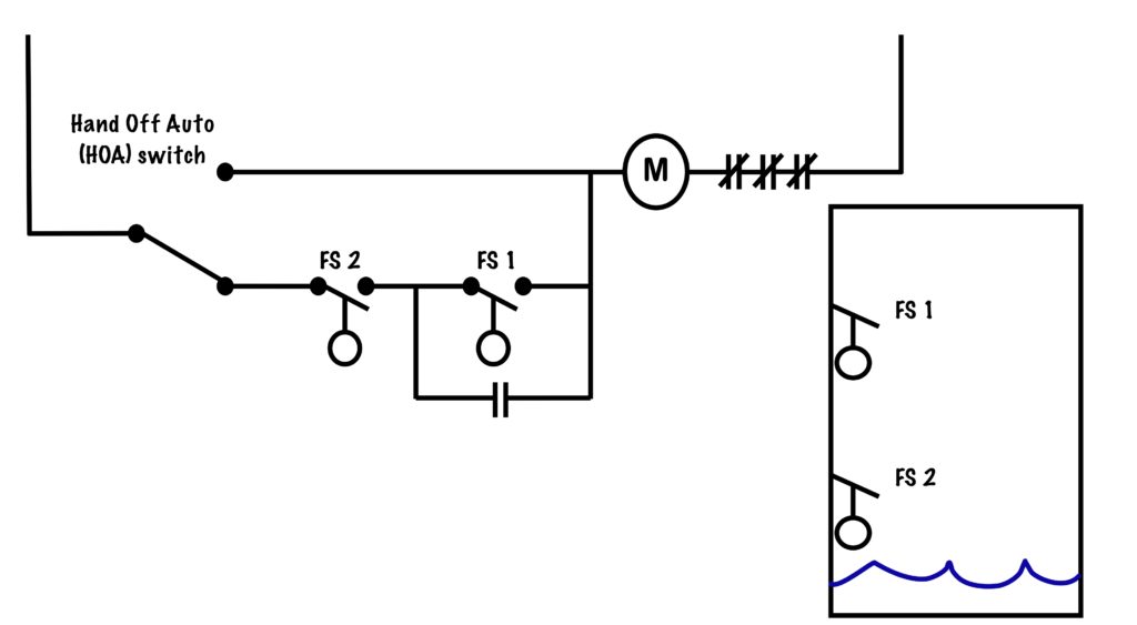
Sump Pump Circuit Basic Motor Control

Float Switch Wiring Diagram For Water Pump Youtube
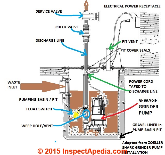
Septic Pump Installation Guide

Liberty Pumps Pro370 Series Simplex Sewage Grinder Systems Installation Guide Manuals
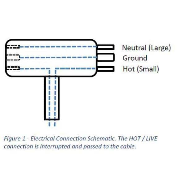
10 Ft Piggyback Float Switch Cable Septic System Sump Pump Water Tank 5 Year Warranty Mercury Free Visible In Water Sa 3100 3 The Home Depot

Operation And Mechanics Of A Float Switch Pumps Uk
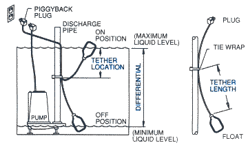
Pump Accessories Information
220 Wiring Float Switch Setup For Septic Effluent Pump Green Tractor Talk

Levelguard Float Switch 110v Ac 15 Ft Cord Lg 12 A Amps Adj 122 F Max Liquid Temp 20x773 Z24801a1z Grainger
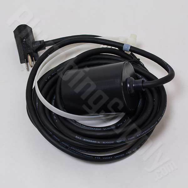
Float Switches For Pumps

Float Switch Wiring Diagram With Manual On Off Switch Youtube
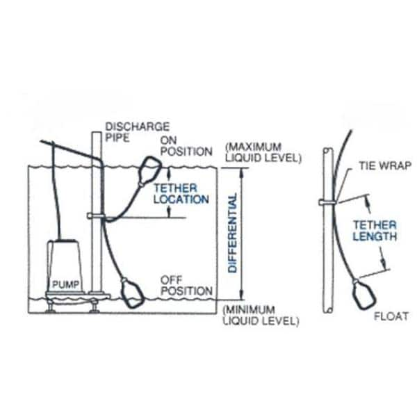
Longest Cord Float Switch On The Market 100 Ft Cable Water Tanks Sump Pumps Septic Systems Sa 2359 33 The Home Depot
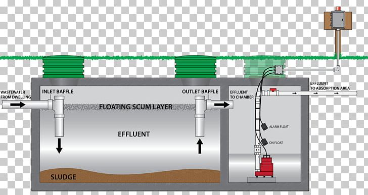
Submersible Pump Septic Tank Sewage Pumping Grinder Pump Png Clipart Angle Diagram Engineering Float Switch Fuel
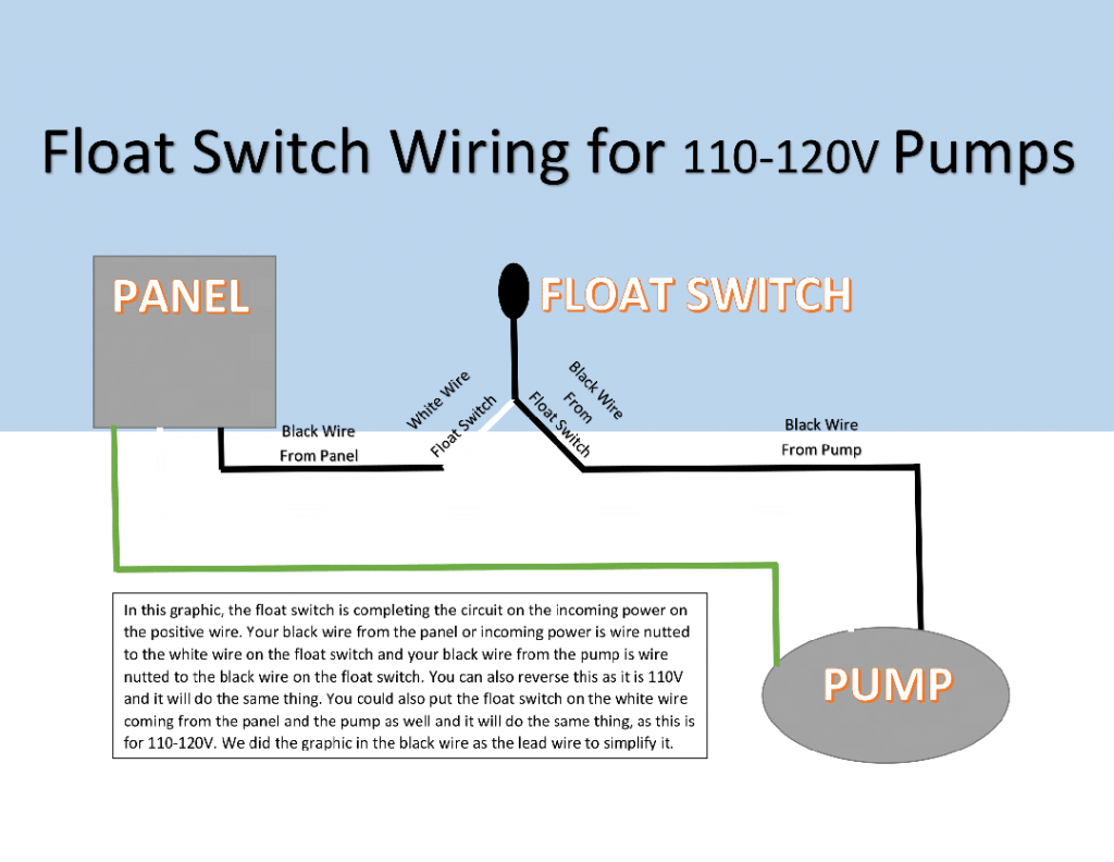
How To Wire A Submersible Pump Aerobic Septic System

Amazon Com Migro Sump Pump Float Switch Water Tank Float Switch For Well Pump Piggyback Power Cable 6 Foot 16 3 Heater Control Cord On Off Electronics